

T.H.O.R. Rover Part 2: First Prototype
This is second part of my build log of the T.H.O.R. Rover. Please see first part (concept and idea) here.
Components.
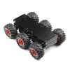
Motors and Frame
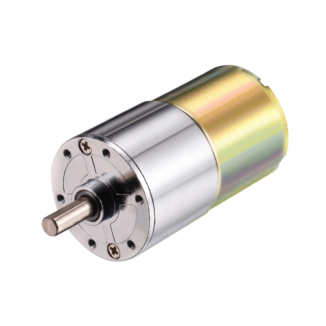
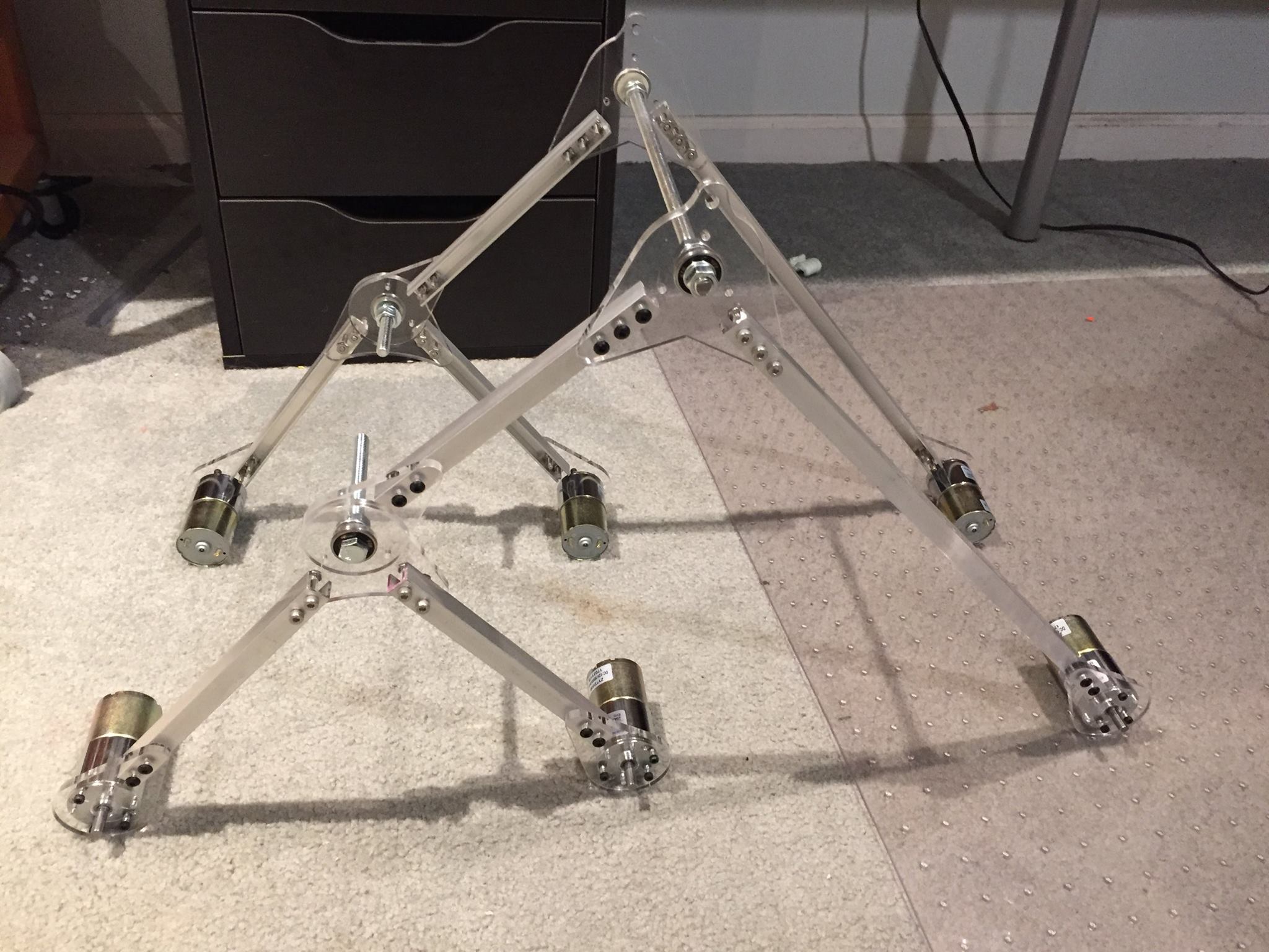
Because I based my rover on rocker-bogie platform with skid steering drivetrain (think steering a tank, turning is accomplished by rotation of one side in one direction and other side in the opposite) I needed 6 motors. I chose 30 RPM geared 12C DC motors. They should provide plenty of torque, and are pretty cheap on Amazon.
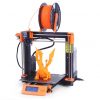
For the frame I decided to use combination of some light aluminum channels and laser cut acrylic parts to keep them together. After I designed frame in Fusion 360 I used my Boss Laser to cut pieces from 1/4″ (6mm) acrylic. I bought some aluminum trim channels at local Lowes hardware store (I think it was 1/4″ wide, smallest I could find) and cut them on my miter saw. I also made a template for drilling holes on each end of the aluminum pieces to match lase cut holes in the acrylic.
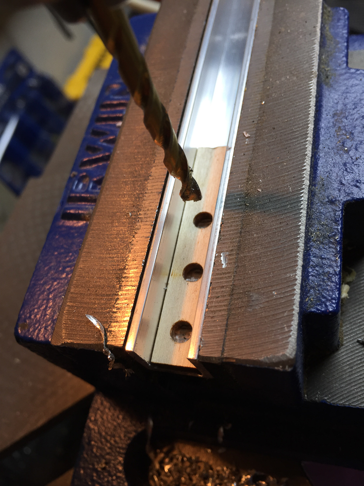
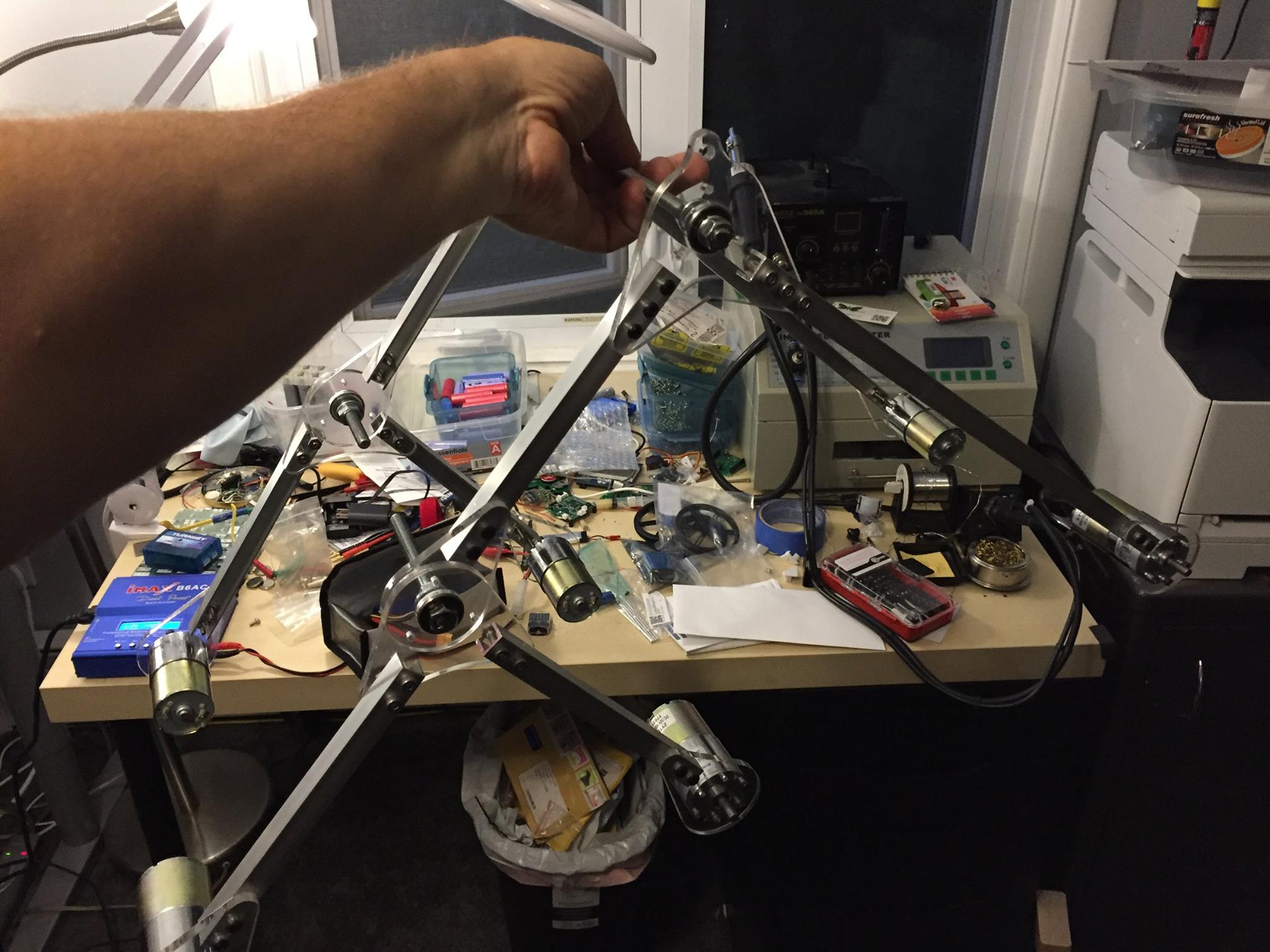
I attached motors to laser cut acrylic parts with M3 screws and then bolted aluminum channels to acrylic. I also used some 608 skate bearings (I had plenty left from the spinners I was making) and using some long 5/16″ threaded rods assembled each of two sides.
What about wheels, you might ask. I decided to use wheels from “Whild Thumper” platform (I mentioned it in part I).

I ordered 6 of those 120mm diameter wheels from Pololu. They come with 12mm hex to 6mm motor axle adapters. Those are attached to the motor shafts with set screws and then wheels are inserted into hex part and bolted from other side.
Electronics

To test prototype I got bare minimum number of electronic components.
- Motor Controller
- Battery
- RC Transmitter and Reciever
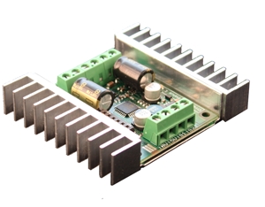
Driving motors is done via Sabertooth dual channel 12A Motor Controller board.
It’s somewhat pricey and while looks very simple, in fact has many hidden features and onboard micro-controller. It has many safety features built in, like polarity reverse protection and can even shut system down if LiPo battery voltage is too low. It has two channels so I can connect 3 motors to one and other 3 to the other. No need to control each individual motors separately. Each channel can handle up to 12A, which is more than enough for me.
I soldered a pair of twisted wire to each motor, and then crimped 3 positive wires together to a “fork spade connector”, followed by 3 negative wires to another terminal. So in the end, I had one positive lead and one negative lead coming from 3 motors on left side, and similarly two connections from the right side motors, 4 in total.
Using terminal block I bolted motor wires to the controller.
For power I got a beefy 5000mA LiPo 3S battery that can provide around 12V.

RC part was a little more challenging for me as I had absolutely no experience building remote controller cars. I had to research about channels, transmitters and receivers. Fortunately it’s all pretty easy. I bough inexpensive RC Car remote transmitter (FlySky FS-GT2B) with 3 channel receiver.
I only needed 2 channels, one to control motors on right side and other one to control left side. Fortunately Sabertooth controller is smart enough to do all the mixing and handles driving directions and turning on it’s own and it even supplies 5V to power receiver. Pretty impressive! I did have to make custom wire connectors because RC receiver module was meant to control servo motors. But that wasn’t too hard.
Putting it all together.

As I had to put all of these components on the rover, I very quickly designed a rough cabin and laser cut it from birch plywood.
I’ve placed long 5/16″ threaded rod thru one side of the frame, thru the cabin and into other side bolting it as needed with nuts. Then I added differential bar (also laser cut) on top of the cabin and connected it to each side of legs with some wood pieces. Differential bar was very very poorly made, as I had only slight idea how it needs to move, so at this state it was only barely holding cabin level.
Test Drive.
Spoiler, it was an Epic Fail 🙂
Once I assembled shaky frame and energized system with LiPo battery, I was happy to find out that my RC controllers actually worked very well. I could drive it forward, and I could drive it backwards. Even with 30 RPM motors speeds was pretty decent. Unfortunately I could not turn it using skid-steering. As wheels began to rotate in opposite directions, whole frame started to creak and twist and almost fell apart. Problem was that frame was very big and not very rigid. Rubber wheels had too much drag and were too far apart. It just couldn’t work. Upset as I was I wanted to try and see at least how it would climb the stairs. It didn’t. Ok, maybe it can just descent? Nope, everything pretty much came apart as I tried driving it down the stairs.
But it wasn’t a total failure. I learned a lot from my prototype, hopefully you will learn from my mistake too:
- Frame needs to be very strong and very rigid.
- There are serious drag issues when you are trying to skid-steer 6 rubber tire wheels
- My stair steps have lip on them, so it might not be possible to climb when with rocker-bogie system even if it was build perfectly.
- Differential bar doesn’t just move back and forth. It also needs to have joints to move a little in all directions.
Having realized all those issues, I decided to try few things to solve them.
Please visit Part 3 of the T.H.O.R. Rover build (hint: it’s about Omniwheels). Coming soon!