

No products in the cart.
Return To Shop


How to add beam combiner to SH-G350 laser cutter
CO2 Laser cutters are insanely cool, but there’s one problem. We cannot see infrared beam, so it’s always a guesswork where laser is actually will hit the work piece. Many laser cutters including SH-G350 come with a red laser pointer attached near head cone, but they are far from accurate. One that came with my machine annoyed me to the point that I disconnected it completely. It never points to where laser is cutting (mine was about an inch off to the side) and it can only be adjusted up or down. Spot gets larger or smaller depending on where your z-table is located. And to make things worse,there was something wrong with mine as it kept on overheating and fading.
So what is beam combiner and why would you want one?

As you can see from the illustration beam combiner is a special lens that only let’s certain wavelengths thru, and reflects all others. In our case Infrared laser beam passes thru it, while visible red laser reflects. By adjusting angle of the lens you can get both beams to travel same path. You can actually see where IR laser beam is going and where it will end up on the table!
No more guessing, where you cut will be. As added bonus this makes it insanely easy to align mirrors. You don’t have to burn pieces of paper anymore! But wait, there’s more 🙂 ZnSe lens will also focus red laser beam, so you can even see if focal distance to the object is ideal!
Besides combiner lens, there’s also a mount that holds it and that’s the tricky part.
There’s really not that many beam combiner mounts out there. I decided on purchasing one made by Light Objects. It’s a great looking mount and it has laser pointer built in!
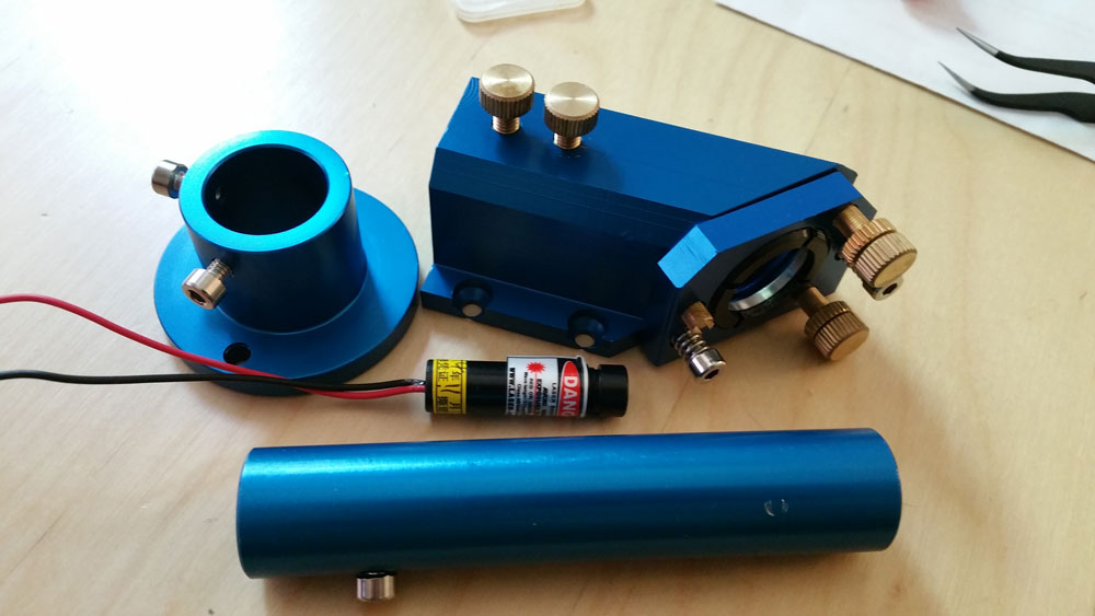
This mount accepts 25 mm beam combiner lens ($85 at Light Object)
Ideally beam combiner should be placed right after CO2 tube, before first mirror. Unfortunately in my machine there’s no space for that. However there was a pocket of open space right after 1st mirror.
Light Object mount was too long to fit in that spot, so I had to modify it. Mounting arm had to go, instead I 3D printed a 90-degree bracket.
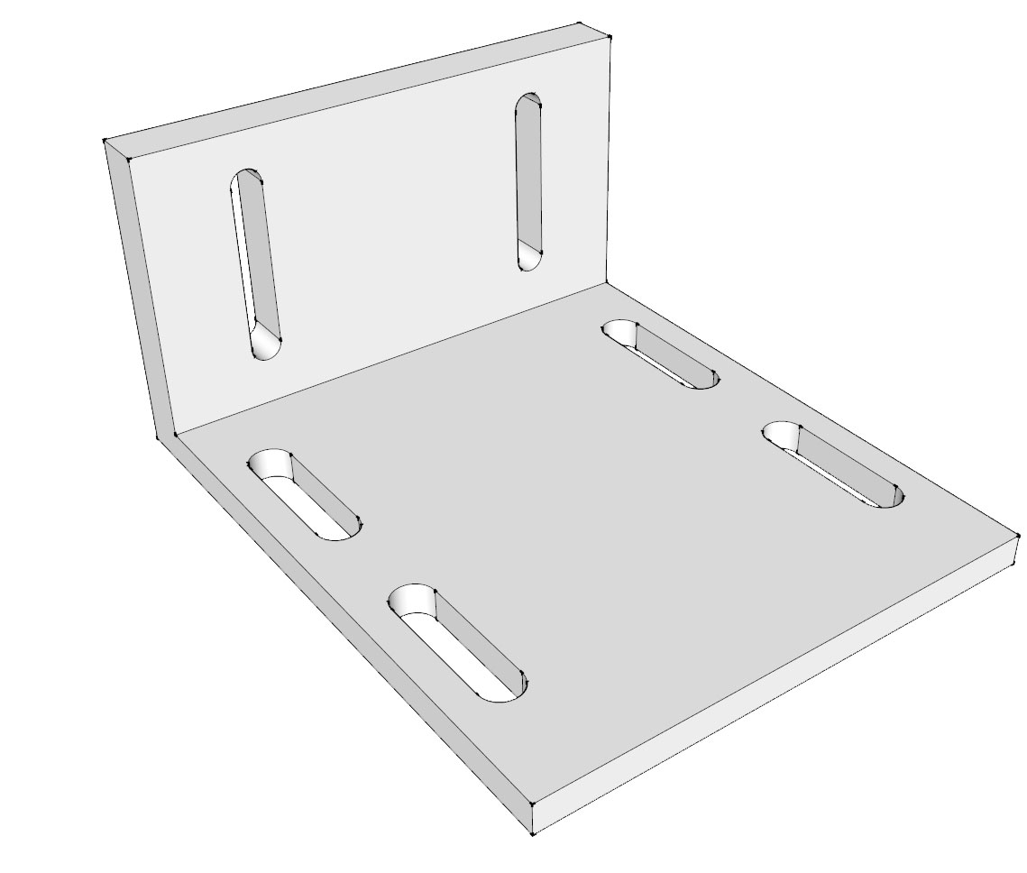
If you don’t have 3d Printer you can easily make one from acrylic or piece of metal. One side of the bracket get’s attached to the machine’s side, which requires drilling two holes thru the metal. Second side attaches to the mount itself. I made long holes so position of the mount can be adjusted.
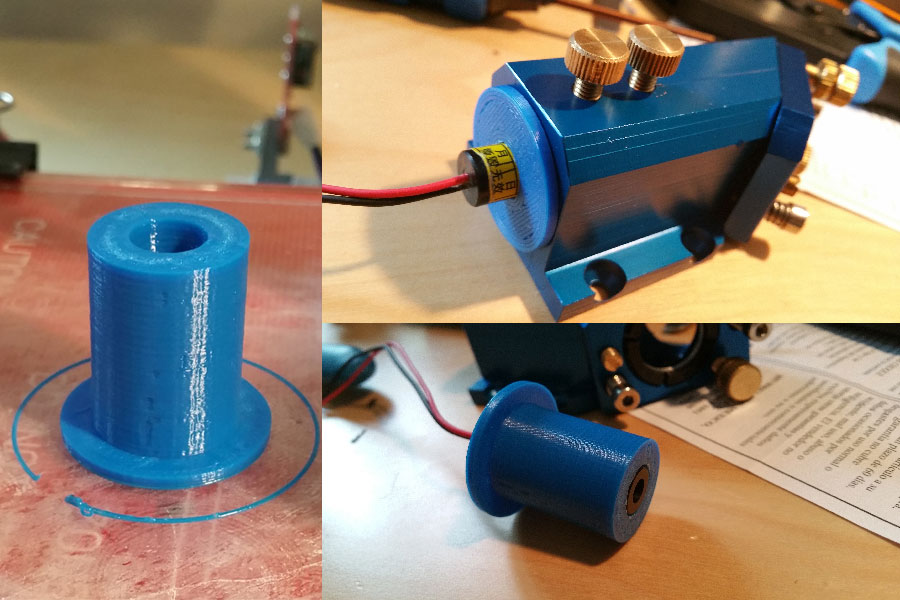
Laser pointer itself is tiny cylinder that normally goes into aluminum arm that holds the mount. But because I was not using this piece, I had to 3D print an adapter to hold pointer securely inside the mount shaft. Alternatively you can use a wooden dowel. It will have to fit inside shaft and then you’ll just drill hole inside to insert laser pointer. Make sure it’s dead in the center!
Here you can download STL files as well as Sketchup model of the mounts.
Mounting.
This part was scariest for me as it involves drilling into metal enclosure of the machine. I gave it a lot of thought and realized that it’s very important to correctly position mount on the “Y axis”. By Y-axis I mean if you are standing in front of the machine it’s direction towards/away from you or back wall of the machine. It’s important because if you mount it too far from the back wall, moving gantry will hit it and something could break. If you move it too far, it will be difficult to adjust mirror angle, as it must be mounted with adjustment screws facing back wall.
If you guess Z axis wrong (up/down) that won’t be too terrible as slots in the mount allow to adjust it up/down.
So let’s find mounting spot. Attach bracket to the combiner holder and move gantry all the way to the back.
Find a good spot where combiner mount doesn’t touch it. Again, remember that lens adjustment screws have to face back wall! Once you find good distance from the back wall, mark bracket edge with vertical line.
Now let’s find approximate height location for the bracket (z-axis). I actually powered red laser with 5V DC power supply to help me in this process. Slowing moving bracket up/down I found where red laser was able to hit 2nd mirror opening. That’s where I marked top of the bracket with horizontal line.
Thanks to long mounting slots, there’s some room for error and later adjustment up or down if you guessed height wrong.
Finally mark and drill one the mounting holes (closest to you) in the side of the laser machine. I used drill just slightly larger than screw I intended to use.
With just one hole you can temporary attach whole thing and check if CO2 laser beam can pass thru the beam combiner lens. Do wear safety glass as there’s some risk of beam bouncing. Just follow mirror alignment procedure by either using sticky white tape or my 3D printer alignment jigs. If you see that laser hits 2nd mirror you are good, unless power is very diminished, which would mean that beam is hitting edge of the combiner mount. In this case adjust mount up/down or left right as needed.
At this point also check if are able to adjust combiner lens so red laser can hit center of the 2nd mirror opening. Remember or mark locations the screws in the mounting slots.
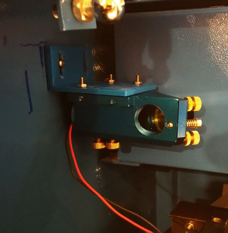
Take aluminum combiner mount off and mark second hole with bracket still being held by first screw. Make sure mount is leveled. Drill second hole.
I found it’s almost impossible to attach aluminum piece of combiner mount to the bracket when it’s mounted inside machine. So take bracket off and mount combiner piece. Don’t forget to secure laser pointer inside. Now attach whole thing to the laser machine wall and adjust as needed. For me I had to move mount all the way to the right at the very limit of the mounting slots. That means there’s room for improvement in 3D model of the mount (i.e. make slots longer or offset them to the right).
Here’s a tip: use some kind of “secure” nut so it doesn’t unscrew on it’s own from vibration. Either nylock nut or spring or star-lock washer should work. (I used nut with attached star-lock washer).
To wire laser pointer I used same wire that powered original red pointer attached to the laser head. I cut wire, removed useless pointer and threaded wire out of cable chains. It was way too long so I cut it, then soldered to the new laser pointer leads (make sure polarity is correct, on mine wire had Red as positive and Yellow as negative). I also used heat-shrink tubing, but electric tape will work. Make sure wire is out of the way of all moving parts!
Aligning beam combiner is stupid easy. It didn’t seem to affect path of the infrared laser beam at all, so I only had to adjust beam combiner lens to bounce red laser beam to the same spot where IR beam would go. For this you’ll need to make some test burns. In theory there should be some diffraction of the beam inside the lens (see pic in the beginning of the article), so your mileage may vary.
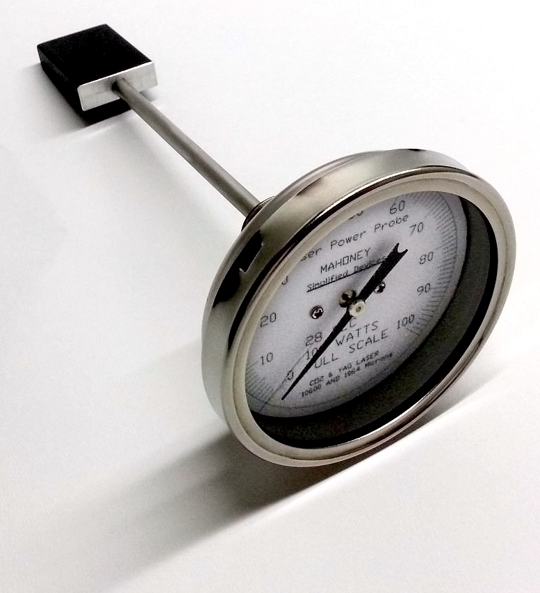
I was concerned about power drop that beam combiner lens might introduce. However after assembling it and making some test cuts, I didn’t notice any power losses. There’s probably some loss, but I think it’s less than 1%. I tested laser beam with my analog Mahoney laser probe and didn’t see any difference before or after beam combiner.


Related posts

Help! Why is my image mirrored!? We have ALL been here. It’s frustrating. The image is mirrored and now your design is screwed up. How... Continue reading

Has this ever happened to you? You’ve created the perfect design in your graphics software, set up your cup on the rotary (hopefully a PiBurn!),... Continue reading

So, you want to run tumblers! But which rotary is best? We asked 50 people with the PiBurn what their favorite rotary was. ... Continue reading

You might already know how versatile PiBurn Rotary Attachment is, but did you know that it can also make Popcorn? Continue reading

I’ve been using RDWorks to send jobs to my Laser machines for many years. Fortunately there’s a new game in town and it’s software called... Continue reading
5 comments on “How to add beam combiner to SH-G350 laser cutter”
Andy P
Hi there. I have just fitted a beam combiner, a Znse type, the visible Red LED will reflect, but also shine through, also I have found that the UV laser light will also do this, requiring me to shield around the lens to prevent damage to surrounding components….is this typical?
bratan
There shouldn’t be any kind of UV radiation emitting from your CO2 tube. Or are you talking about IR light? If you have IR light reflecting from beam combiner lens, there’s something not right with that lens. It should not do that…
Doug
Looks to be about 2% loss of IR power is normal.
http://www.iiviinfrared.com/CO2-Laser-Optics/beam-combiners.html
adrian
hey
question – the lens on my machine does not allow red light to pass through – this means a combiner will not work
bratan
Are you sure about that? What kind of lens do you have? All ZnSe should allow red light thru. If you know for sure your doesn’t, then you can’t use beam combiner, at least not one with red laser…