

No products in the cart.
Return To Shop


How to add ammeter to 50W Chinese laser cutter from eBay
Ammeter add-on was on my to do list for a long time. It’s important to know what current is flowing thru your CO2 tube so you don’t shorten it’s life. Ammeter measures current and in case of this SH-G350 machine you’ll want ammeter rated in the 0-30 or 0-50mA range because most CO2 laser tubes run under currents under 25mA.
WARNING!!!

There’s extremely high voltages inside laser cutters! It can kill you in an instant. Power off and UNPLUG your machine from AC outlet before doing anything and wait for a while (at least an hour) as power supply may retain deadly voltage in the capacitors even after you unplugged it. I will not be held responsible for anything that might happen to you, so please only do this at your own risk. Also I’m not an expert and don’t have electrical engineering degree so anything I say in this article could be wrong.
Please keep in mind that by making modification to your laser machine you most likely will void any warranty you might have.
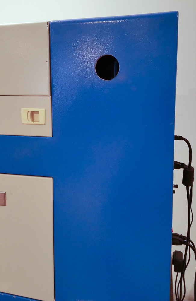
And final warning. If you do use hole saw, you’ll probably have “extra” opening not covered by your ammeter. At least that’s what happened to me. I covered it with some tape for now, but you might want to cut some plug/cover later on…
Picking Ammeter
I highly suggest to get an analog ammeter rather then digital one. Digital ammeters are really cool, however they require separate power source (usually 5V). But that’s not a big issue. Problem with digital ammeters that they are slow so you might not even see change in current if laser pulse is short. Analog ammeters show current changes in real time.
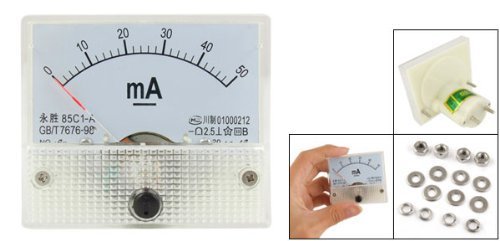
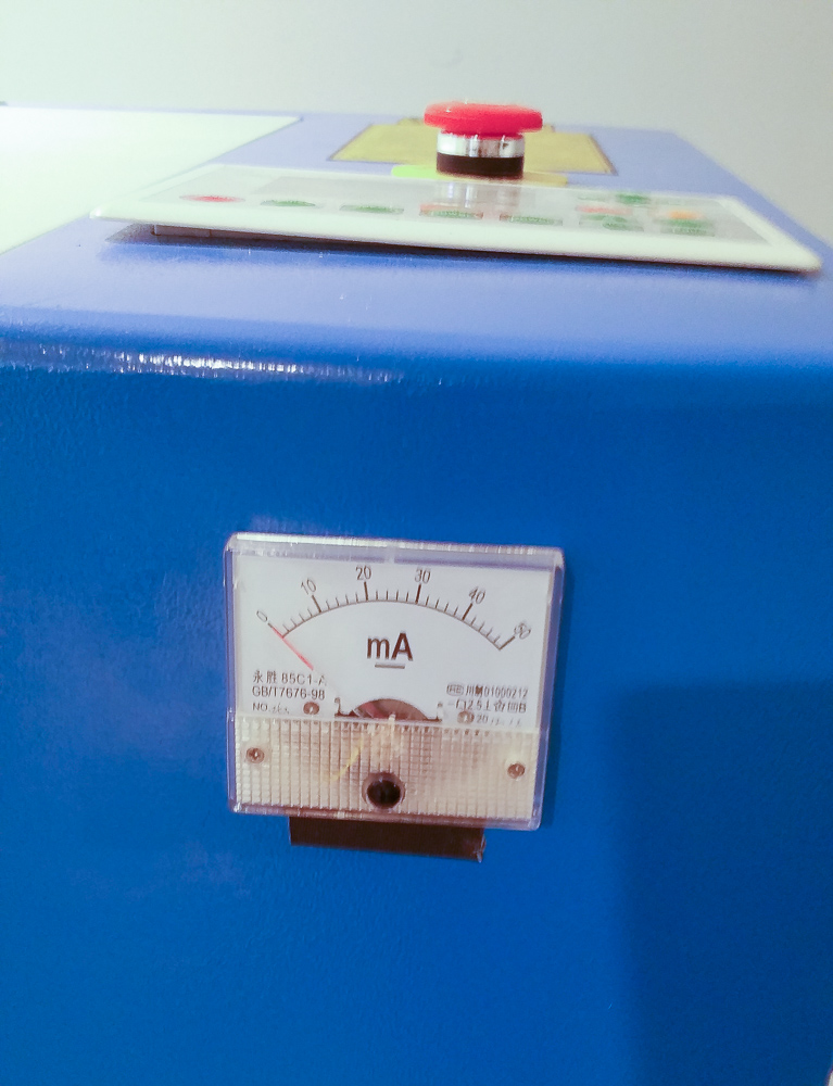
I bought a really cheap SMAKN 85C1-A DC 0-50mA ammeter on Amazon. It might be out of stock at this time, but they are pretty much the same. Just pick a DC (not AC) one in the 0-50mA range, as it will never go over 30mA mark anyway.
Other parts and tools you will need
- Long piece of 14-18 awg wire
- Heat-Shrink tubing
- Solder
- 1.5 inch bi-metal hole saw (diameter might be different if use different ammeter)
- AC Powered drill (battery powered might not cut it)
- Needle nose pliers
- Wire strippers
- Soldering iron
- Round file
- Paper towels
- Vacuum cleaner
Step 1: Prep
Find a suitable place for ammeter. Make sure there’s nothing that’s already in the machine behind that space. On my SH-G350 I had plenty of empty space in the front top region so that’s where I decided to install it.
Triple check that machine is unplugged and there’s no residual voltage left in power supply.
Cover power supplies, etc. inside from getting metal shavings. These might cause shorts and all kind of damage if they get inside electronics. I used paper towels to cover power supply.
Step 2: The thrill of drill
There are few options to attach ammeter. Some choose to make enclosure for it and attach to the outside of the case. This is non-destructive method. I decided to permanently install meter by drilling several holes in the metal of the laser cutter’s case.
If you inspect back of the ammeter (assuming yours is same as mine), you will see a long stem with 2 screw posts where you will connect wires, as well as 2 more mounting screw posts.
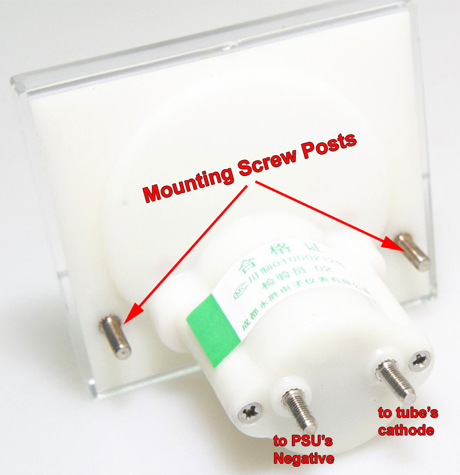
I chose to drill big hole for the “stem” and two smaller ones for the mounting screws. Unfortunately stem is oval in shape, so if you drill round hole it will leave some opening that will be visible when ammeter is installed. That’s the sacrifice you’ll have to make 🙂 Alternatively you can drill several smaller holes and file them down until they match shape of the stem.
Pre-drill small pilot hole (optional but recommended). Then using your 1.5″ hole saw with pilot bit attached, drill big hole.
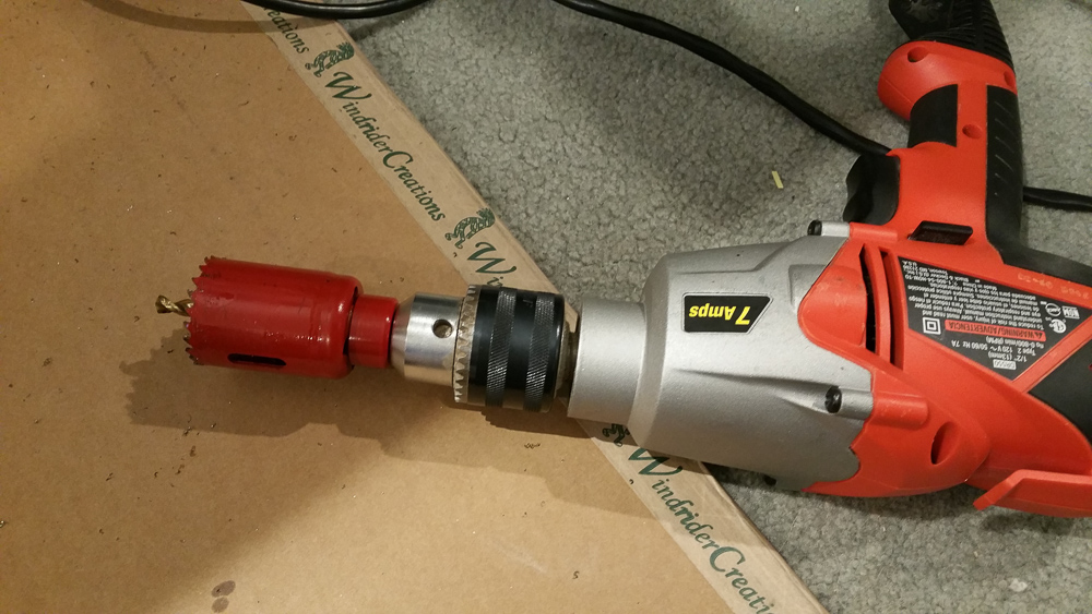
Some tips. Add cutting oil on the saw teeth first, it will make drilling faster and will do less damage to your hole saw. Make breaks to let saw cool down a little and remove metal shavings. If your saw is dull it will take really long time…
After big hole is drilled, you might want to deburr sharp edges with file. Mark spots for drilling smaller mounting holes. I put some acrylic white paint on tips of the ammeter’s mounting posts and positions it in the hole, making marks with paint on the metal. Or use any other measuring tools like calipers to find where holes should be.
Pick a drill bit slightly larger than mounting screw posts and drill at marked locations.
Now try and see if ammeter fits inside. In my case it didn’t because stem was slightly wider in two places. I used round file to elongate hole until meter fitted.
Use vacuum cleaner to clean the mess you created and carefully remove paper towel from insides of the machine.
Step 3: Wiring
Wiring is actually not that difficult. You will place ammeter on NEGATIVE wire. Without ammeter negative wire goes from Power supply to the Negative terminal (cathode) of the CO2 tube. What you are going to do is cut this wire and splice ammeter between both ends of “cut” wire. Current will be going thru CO2 tube’s cathode, into ammeter 1st terminal, and then out of it’s second terminal and finally into power supply. This is shown on the rough schematic below:
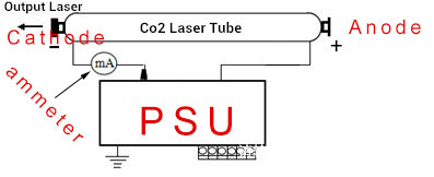
Ammeter’s terminals usually have some kind of marking. If you see “-” sign near one it means that end goes to power supply, and other goes to CO2 tube’s cathode. But if you accidentally reverse polarity, ammeter’s arrow will jump to negative space (below 0) and as long as you send very low current you probably won’t damage it.
Hope this makes sense.
Now let’s make physical connections. Find place where negative wire from PSU spliced with wire going to CO2 tube’s cathode and cut it somewhere there, but you’ll most likely want to have a longer piece of wire coming from PSU because it needs to reach ammeter which attached in the front. But no worries if it’s too short, then you’ll just need to solder extra piece of wire (don’t use wire thinner than 20 awg) long enough to reach ammeter’s negative lead.
Don’t forget to use a piece of heat-shrink tubing or electrical tape to insulate that joint.

Place a washer that came with ammeter in to negative post. Take negative wire from PSU (with optional extension), strip the end, and wind around ammeter’s negative post. Insert second washer on top. Then insert spring washer and finally screw in nut until wire is held securely.
Now cut of good thick wire (I used 14 AWG speaker wire), and cut it so it can reach all the way from ammeter to the wire connected to CO2 tube’s cathode. Attach it to remaining terminal of the ammeter just like wire from PSU.
Strip second end and solder to the wire coming from CO2 tube’s cathode. Cover joint with electrical tape or heat-shrink tubing.
Step 4: Pre-Test
Before permanently attaching ammeter, make sure that you wired it correctly and polarity is not reversed. Put it somewhere securely so it’s terminals are not touching anything.
Set laser min/max to smallest possible power setting at which your machine fires. On mine it was 10%. Do a pulse and see which direction arrow on the ammeter moves. If it tries to move below zero, you wired it in reverse. If that’s the case unplug machine, wait for PSU to discharge and fix wiring issue by swapping wires on ammeter’s terminals.
Step 5: Finish installation and final test.
Unplug machine and wait for power to dissipate from PSU.
Install ammeter using mounting screw posts, washers and nuts. I used needle-nose pliers to tighten nuts.
Now test your machine and check which current you get at each power setting. Do not go above 20mA if you still have factory tube (50W machines actually come with 40W CO2 tubes).
Here are my results:
| Power | Current reading |
|---|---|
| 10 % | 4 mA |
| 20 % | ~8 mA |
| 30 % | 8 mA |
| 40 % | 14 mA |
| 50 % | 16 mA |
| 60 % | 18 mA |
| 70 % | 20 mA |
| 80 % | 20 mA |
I didn’t go over 80% because my tube can’t handle it.


Related posts

Help! Why is my image mirrored!? We have ALL been here. It’s frustrating. The image is mirrored and now your design is screwed up. How... Continue reading

Has this ever happened to you? You’ve created the perfect design in your graphics software, set up your cup on the rotary (hopefully a PiBurn!),... Continue reading

So, you want to run tumblers! But which rotary is best? We asked 50 people with the PiBurn what their favorite rotary was. ... Continue reading

You might already know how versatile PiBurn Rotary Attachment is, but did you know that it can also make Popcorn? Continue reading

I’ve been using RDWorks to send jobs to my Laser machines for many years. Fortunately there’s a new game in town and it’s software called... Continue reading
13 comments on “How to add ammeter to 50W Chinese laser cutter from eBay”
Gerard
Thanks for the good explonations about placing and wiring the mAmp-meter
Drkstr318
Actually to find out what your max mA you can run on you tube look on the tubes manufacturing site for the model and it will guide you in the right direction. Like mine came w/ a LS SEA tube model F4 they say no higher than 30mA but for best tube life stay around 28mA.
bratan
Yeah that will work if you know make and model of your Co2 tube 🙂 Mine had no indication whatsoever so I had to guess… I think they removed it so I customers won’t know that their 50W machine actually has 40W tube 🙂
Charlie
Do you put any type of insulating material over the connections? Just wondering if you worry about it arcing to the case…
Charlie
I mean beyond the heat shrink. Like silicone maybe?
bratan
No, I didn’t put any insulation to ammeter connections. It’s only ground wire, it should already be connected to case I think…
Charlie
Great! Thanks for the advice. Now I hope when I get the new tube, that is the problem and not my psu…nervous.
Charlie
How do you know what the limit is of your tube? I have a 50w tube which I’m pretty sure I killed today by running it at 80% power for long periods of time. I have no idea what my power supply is rated (?) at, or if there is even a way to figure that out?
bratan
Just don’t go over 20mA for extended periods of times. This is close to the limit for most CO2 tubes as far as I’m aware. Measure at which setting (percentage) your machine reaches 20mA (i.e. 60%) and just don’t go over this number… Treat it as your new 100% power 🙂
Thomas
cool! read your comment to mine here: https://vimeo.com/120212426#comment_14410806
so, what 60w tube do you recommend?
bratan
I got “SP” brand from LightObject.com
Adam
Love it man! I have one identical to that and I found out the hard way that it was a 40 watt power supply and a 40 watt tube. After finding that out I contacted the supplier and demanded they shipped me a 50 watt tube and a 50 watt power supply I told him that was wrong of their company knowingly shipping 40 watt tubes and power supplies in 50 watt machines. Because the price difference between 40 watt 50 watt is big I just got the power supply in today do you think I will have to adjust any firmware
bratan
Nah you can run it as is. Just keep an eye on ammeter, don’t go above 20mA. If it shows 20 mA at 65% power, that’s your ceiling.